A slip-casting machine for a ceramics studio
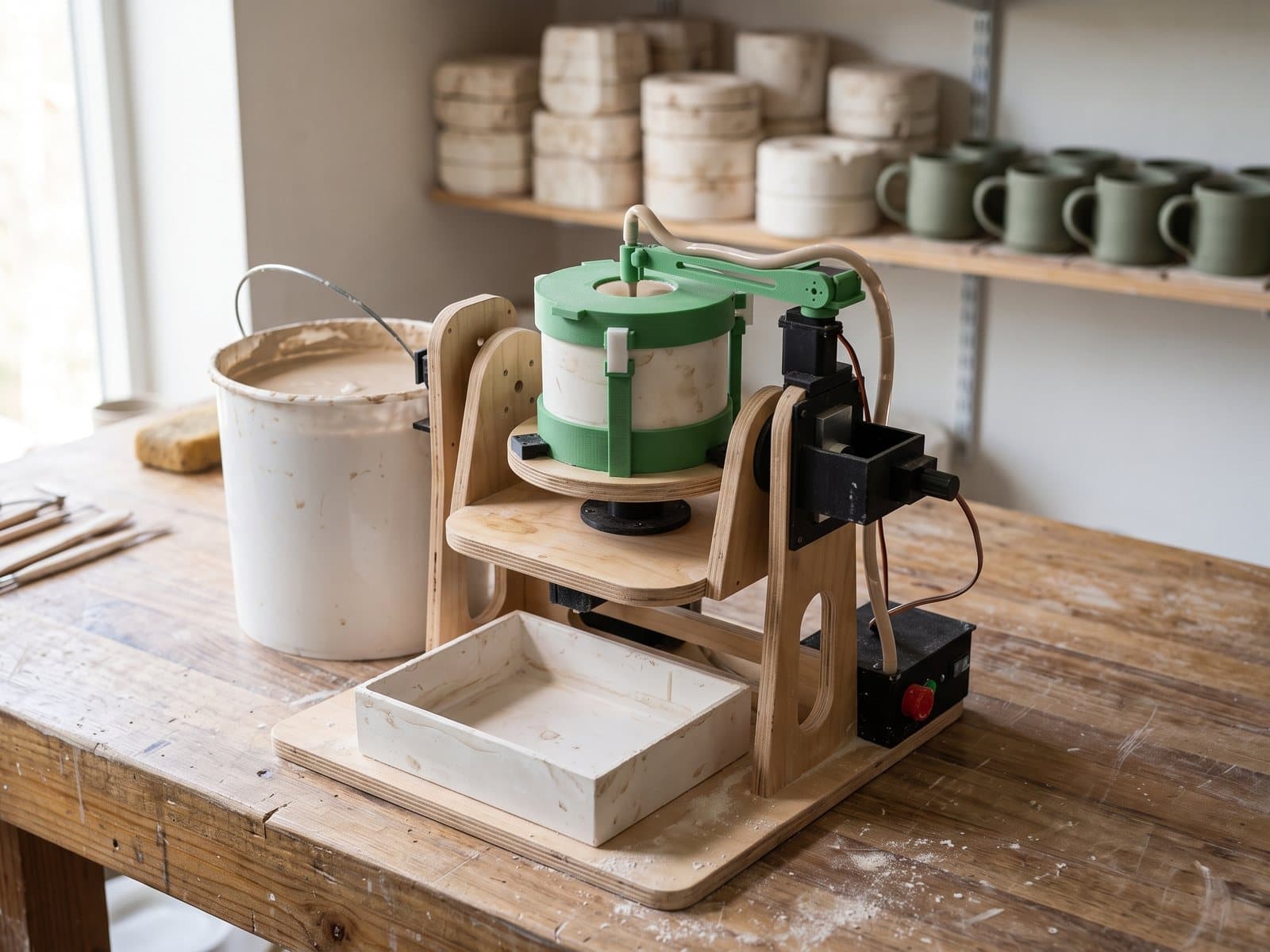
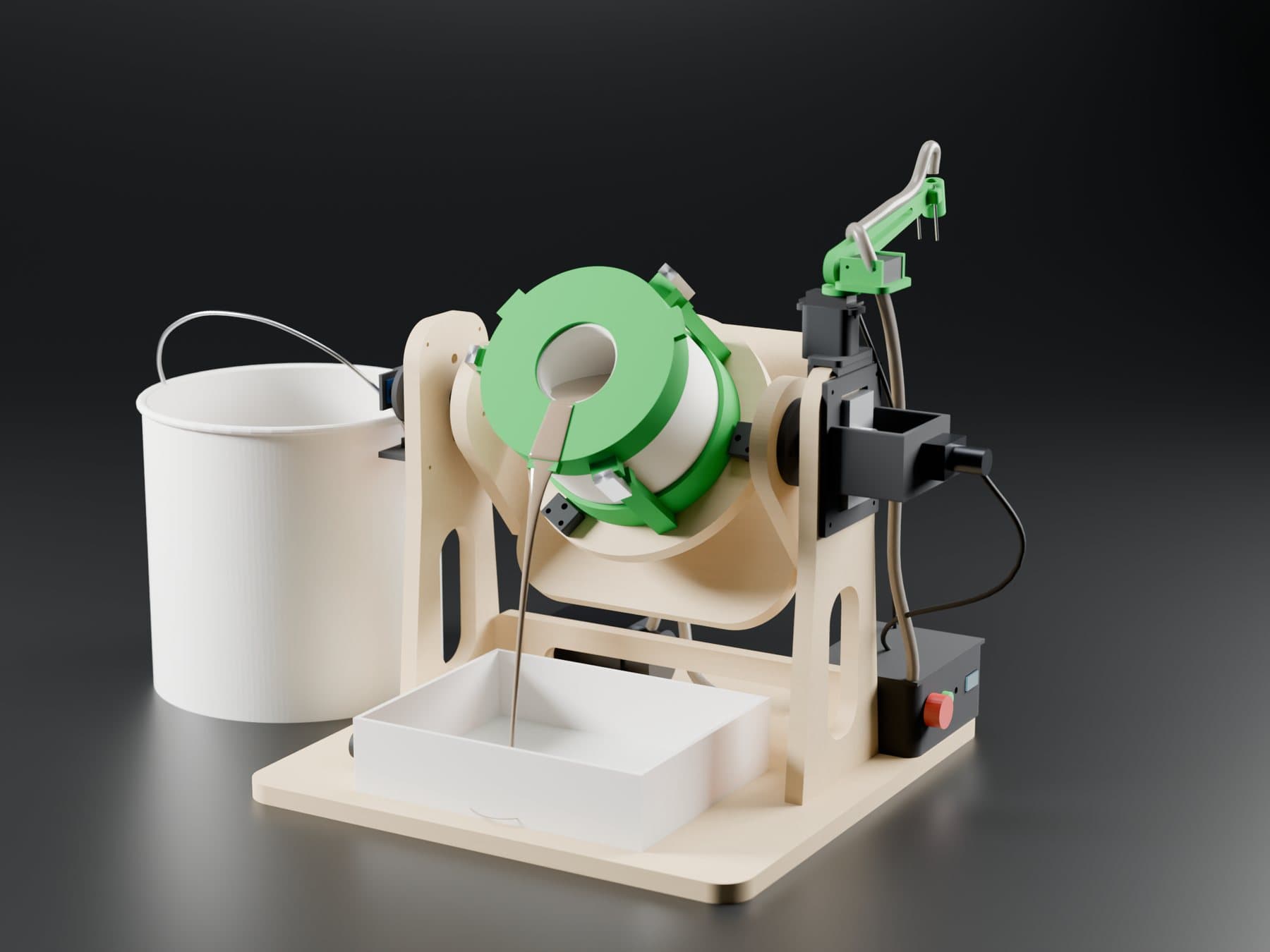
Ceramics studios cast mugs by hand: they pour slip into a plaster mould, watch the clock, tilt the heavy mould and drain the excess. We designed a station that runs the whole cycle on its own and repeatably: it fills the mould up to level probes, tops up as the plaster absorbs the slip, tilts the mould at a controlled speed and spins it while draining. The full package in two days: 3D model, physics, electronics, compiled firmware, technical drawings and a build manual.
Problem
Slip casting is simple in theory: the plaster draws water out, a clay shell builds up on the walls, the rest of the slip is poured out and a hollow mug remains. In practice it is heavy, repetitive work: a mould full of slip weighs over 5 kg, the dwell time sets the wall thickness, and draining too fast splashes. The machine had to run the whole cycle by itself, fit on a studio bench, work in a wet environment and be buildable from plywood, 3D prints and low-cost modules.
Outcome
The machine is ready for a prototype build: 19 kinds of printed parts, 6 plywood panels, a bill of materials, a wiring diagram and firmware. Next up: testing the pump on real casting slip and a mould for the studio's own mug shape. Every parameter (mug, mould, motors, speeds) lives in one script, and the model re-checks collisions and recalculates the physics on its own.
- 01A frame-by-frame analysis of a video of an existing machine: what tilts, what spins and where the hollow comes from. Conclusion: tilting and spinning the mould while draining is enough for a regular mug; a plaster core is only needed for double-walled ones.
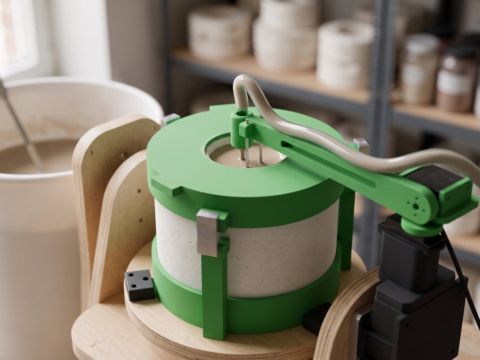
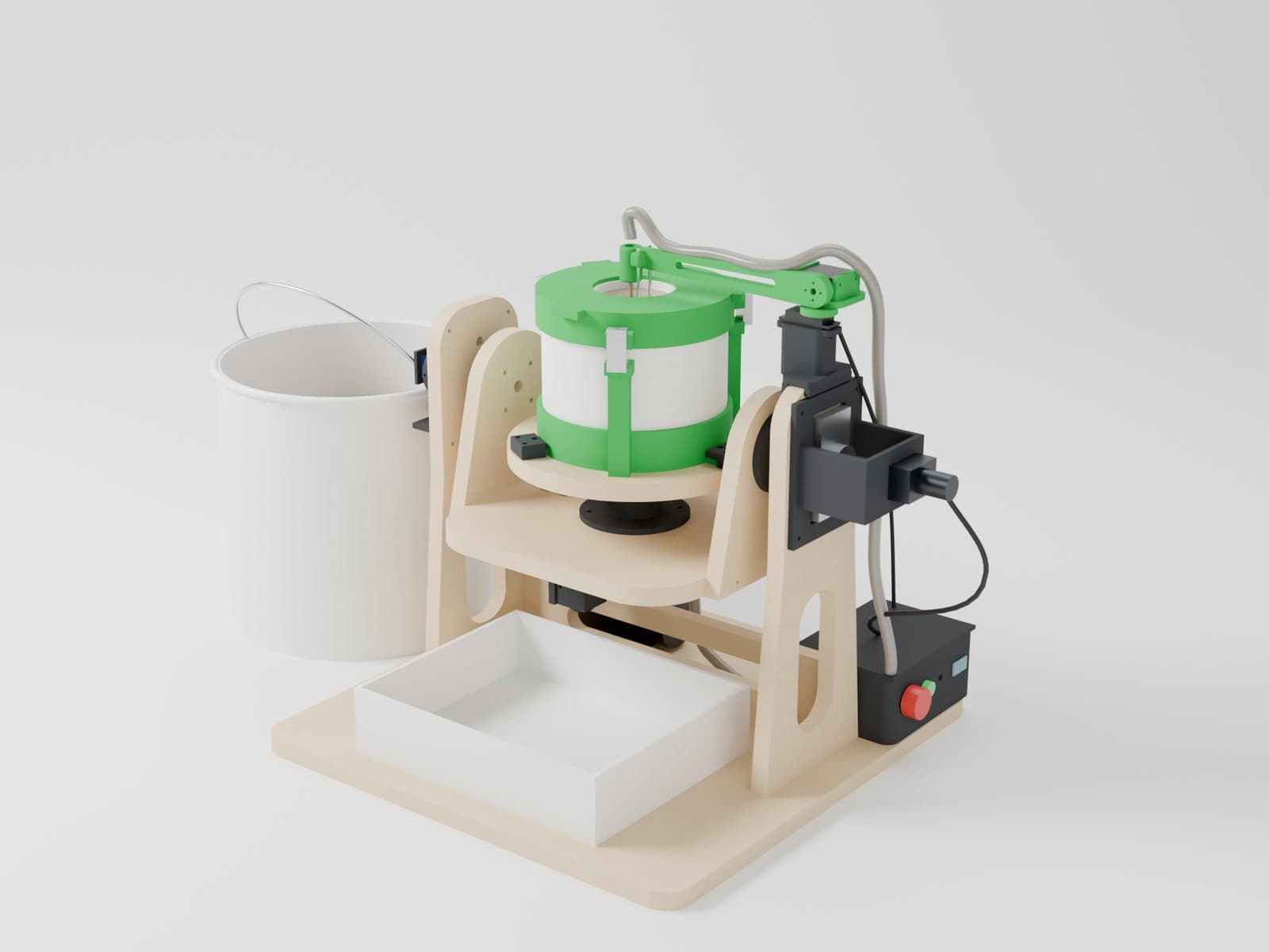
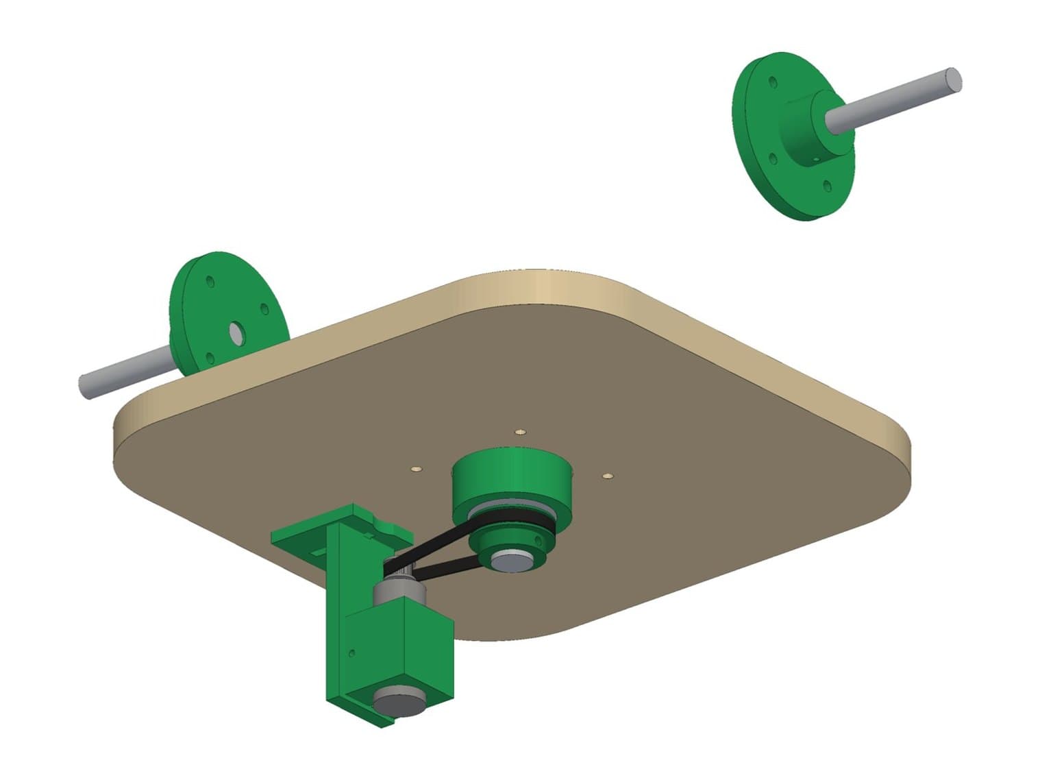
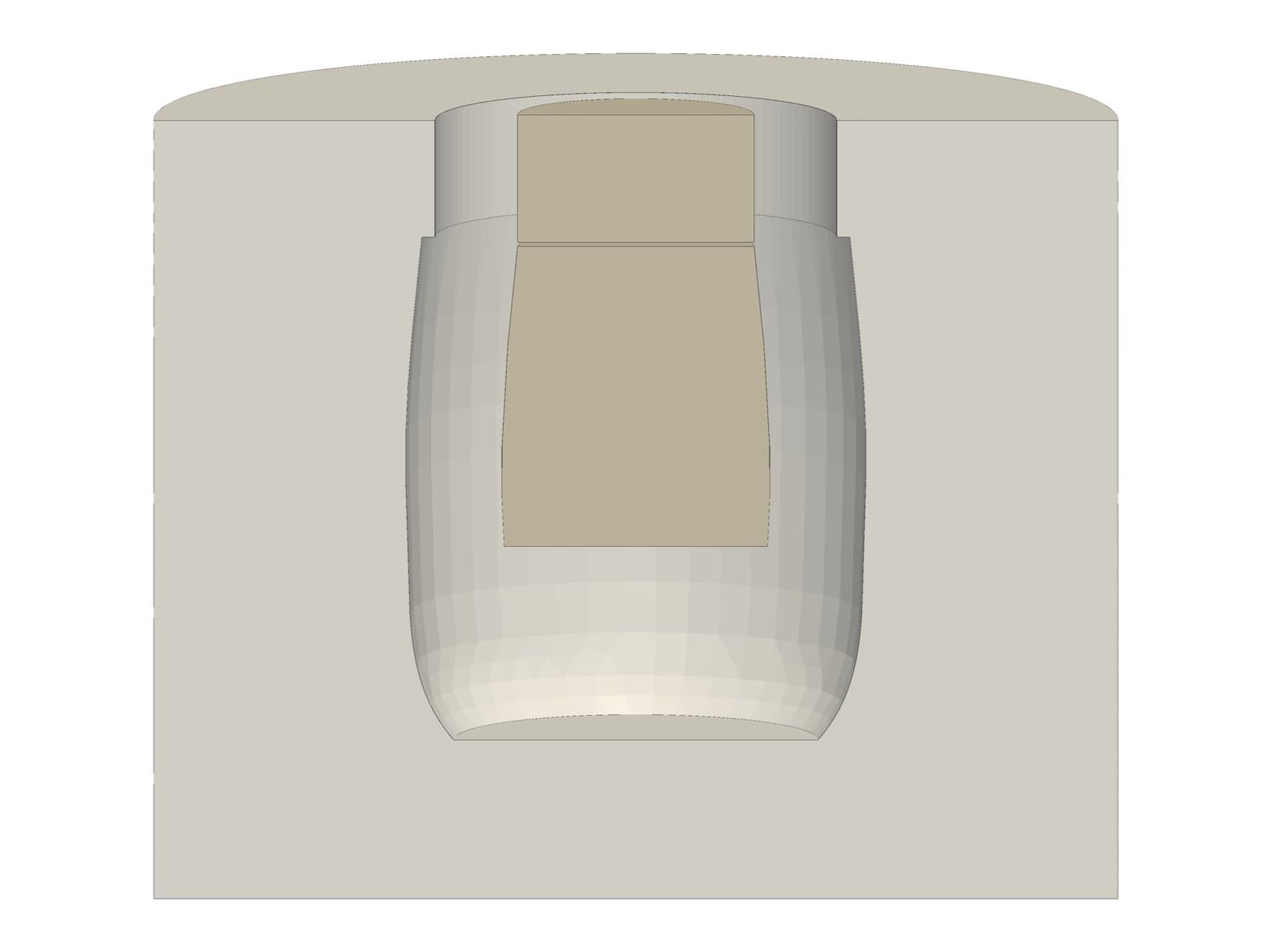
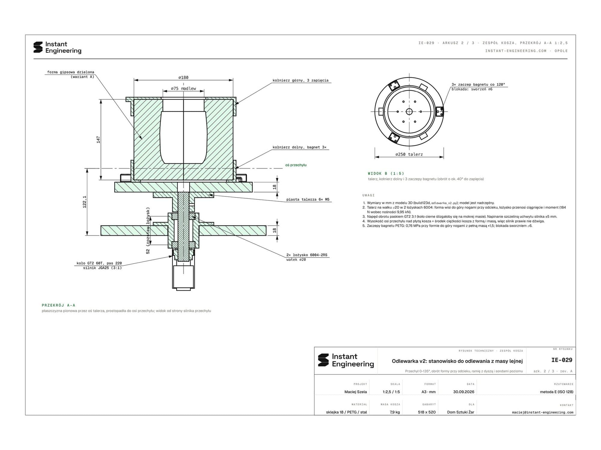
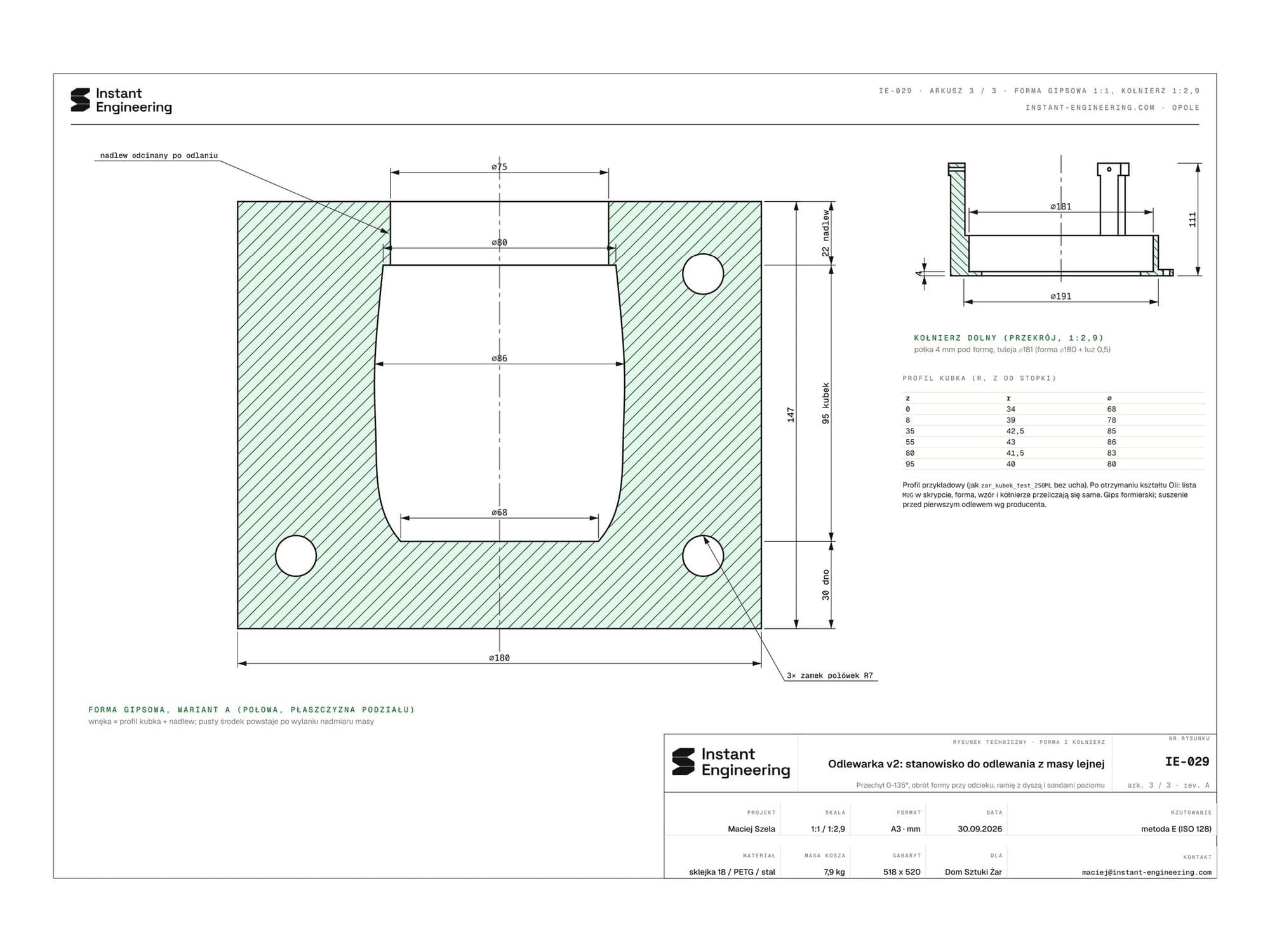
- 02A parametric model in build123d. The mould is generated from the mug profile, printed collars lock with a bayonet, the cradle runs in KFL bearings, the turntable sits on a ⌀20 shaft in two 6004 bearings, spun by a 3:1 GT2 belt. Changing the mug shape regenerates the mould, the printable master and the plaster casting box.
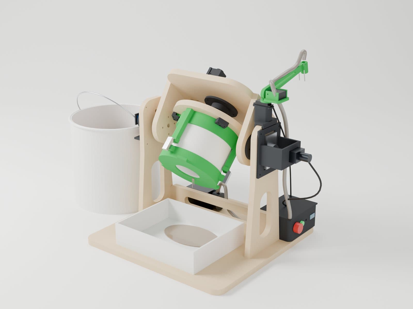
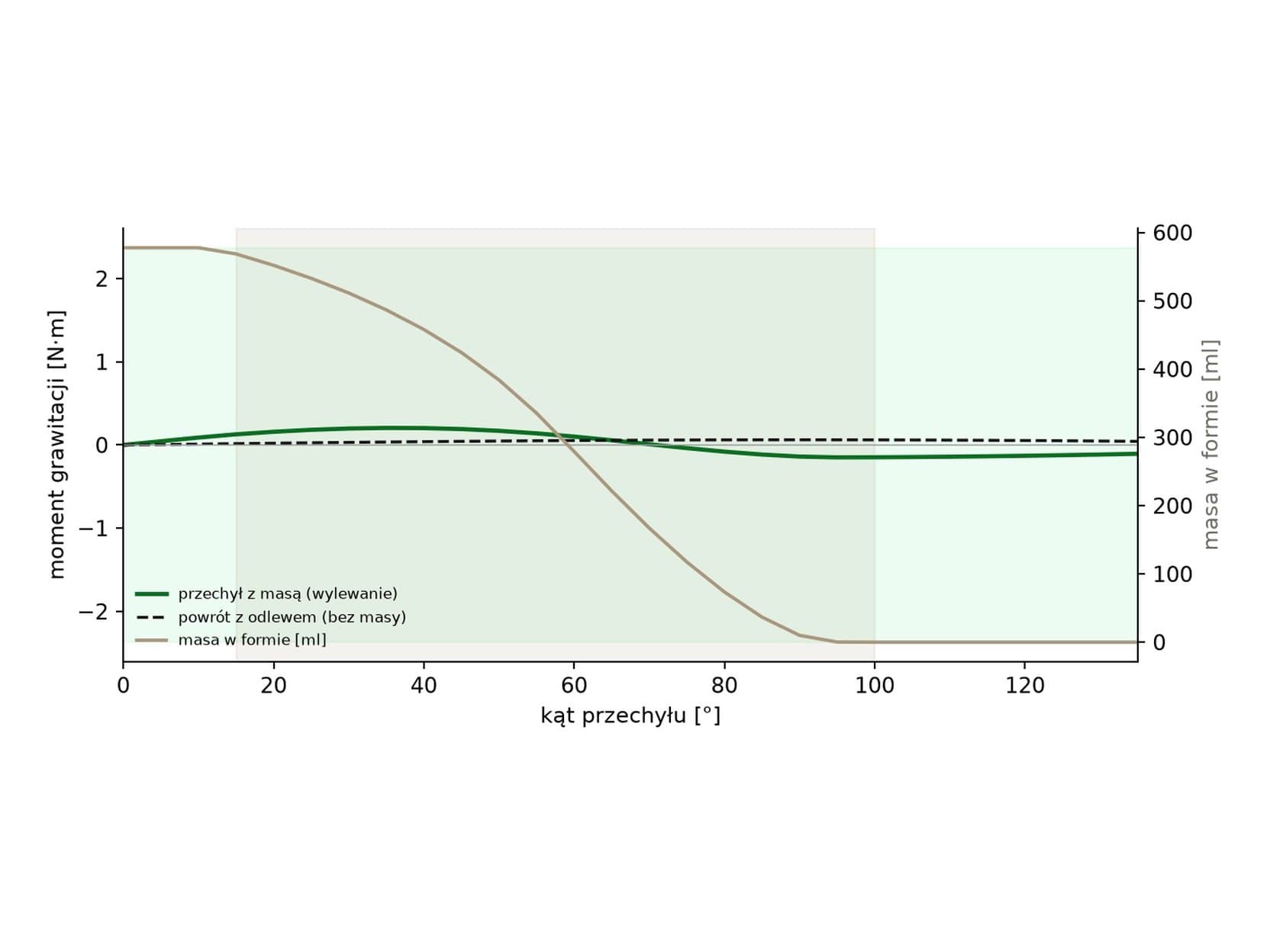
- 03Physics instead of guesswork. The slip is simulated every 5° of tilt (level liquid surface, spilling over the rim), along with the mass and centre of gravity of every part. The tilt axis is placed so the largest torque in the cycle is as small as possible: 0.2 N·m, with the motor sized for 2.4 N·m. The slip pours out between 15° and 95°, so the machine slows to 4°/s there.
- 04Collision checks across the full range of motion: tilt 0-135° every 15°, the complete path of the nozzle arm (it lifts 12° first, then swings 90° aside) and every part at rest. That caught and fixed two mistakes before building: the arm swung through the mould, and the drip tray was meant to drain uphill.
- 05Electronics and firmware: an ESP32, three DRV8871 drivers, an AS5600 angle sensor, slip level probes, two servos and an emergency stop that cuts the 12 V motor supply in hardware. The firmware runs a tilt speed controller and automatic topping-up. Compiled in PlatformIO.
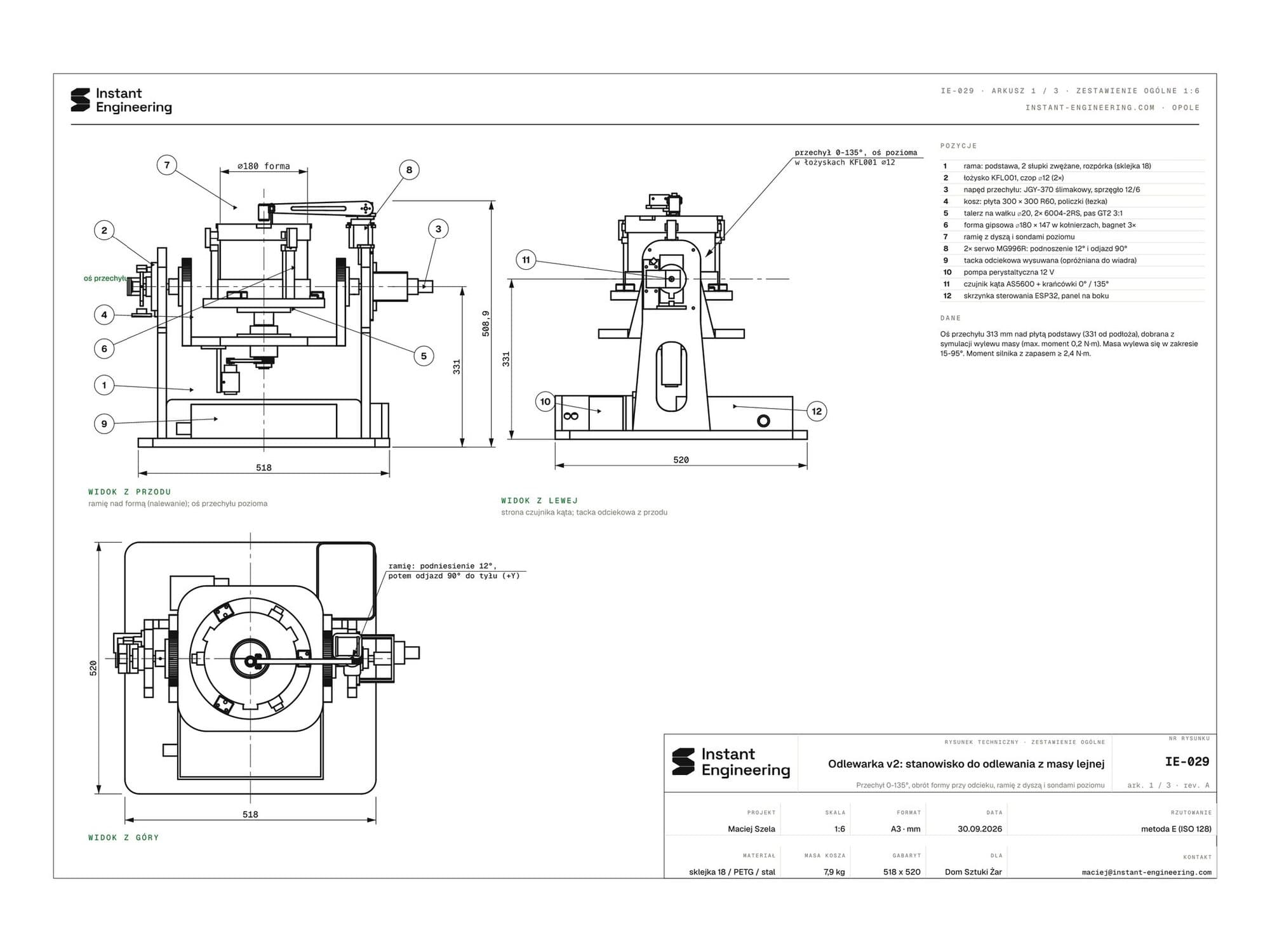
- 06Build documentation: technical drawings IE-029 (3 A3 sheets), a manual with a bill of materials and requirements taken from the calculations, Blender renders from the model (the slip stream computed from the flow rate) and in-studio visualisations.
Specifications
IE-029- Status
- Design, prototype in preparation
- Footprint
- 518 x 520 mm, height 49 cm
- Mould
- Plaster ⌀180 x 147 mm, split
- Tilt
- 0-135°, max. torque 0.2 N·m
- Control
- ESP32, AS5600, level probes, 2 servos
- Design time
- 2 days: model, physics, firmware, drawings