CAD design and DfAM
Designing parts and enclosures for 3D printing and production
Design for additive manufacturing (DfAM) means designing a part for the process that will make it, so the first print fits and works. Instant Engineering, based in Opole and working across Poland, takes an idea, a sketch, a photo or an unprintable model and turns it into a production-ready CAD file, along with a clear recommendation on material and process.
A file is not the same as a design
Most enquiries start with a question about printing. The real problem usually sits earlier: walls that are too thin, a thread that will not come out, a hole with no clearance, a shape that only prints on a forest of supports, or simply a photo and a dimension on a scrap of paper. You can print a file like that, but the part will not fit, will crack on assembly or will cost three times what it should.
So we start with the design. We talk about what the part has to do, where it works, how many you need now and how many next year. Geometry, material and process follow from that. A well-designed part is cheaper in every unit after the first, and it does not need redesigning when the volume grows.
We mostly work with companies: maintenance teams, manufacturers, design engineers, workshops and studios. We also take on private commissions when the part genuinely has to work, not just look good.
When it pays to commission a design
- You have an idea, a sketch, a photo or an old part, but no CAD model.
- You have a model, but it is unprintable: an STL mesh from the internet, a visualisation model, or a part designed for machining.
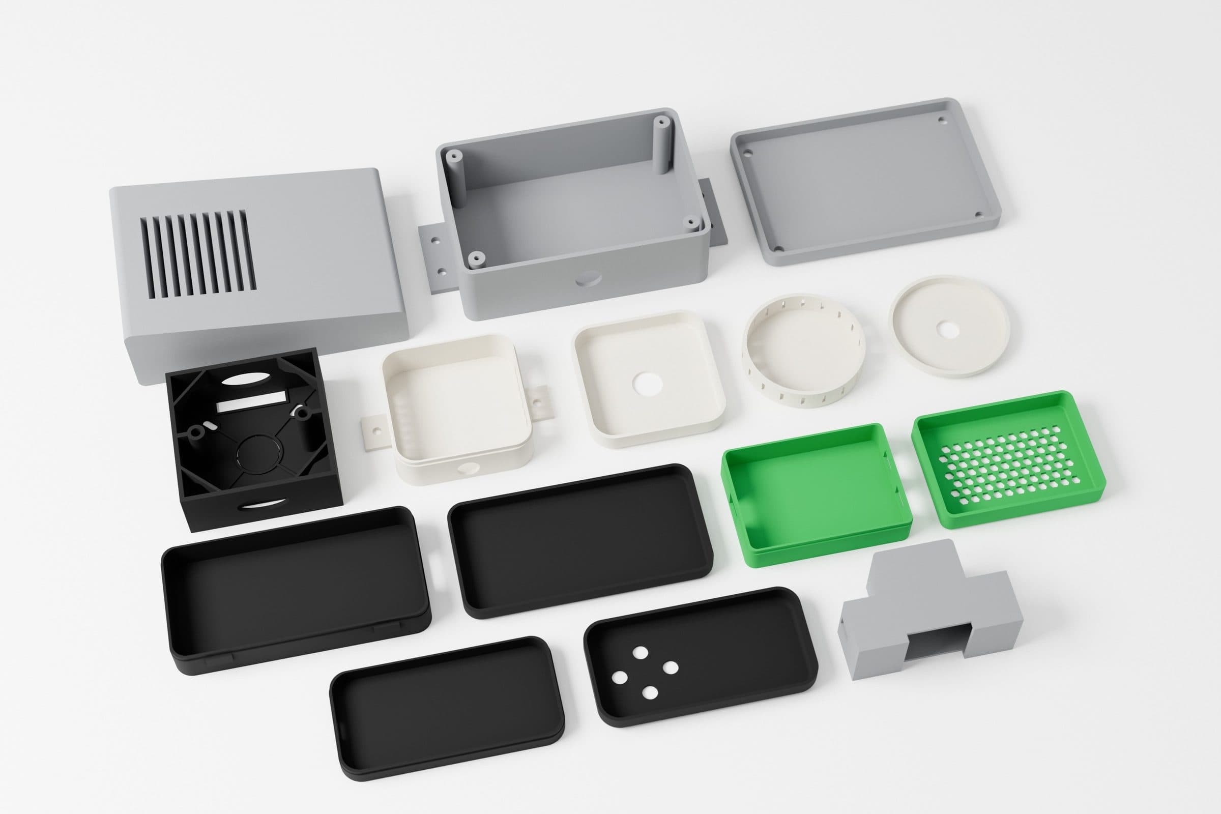
- You need a custom electronics enclosure built around specific boards, connectors and mounting.
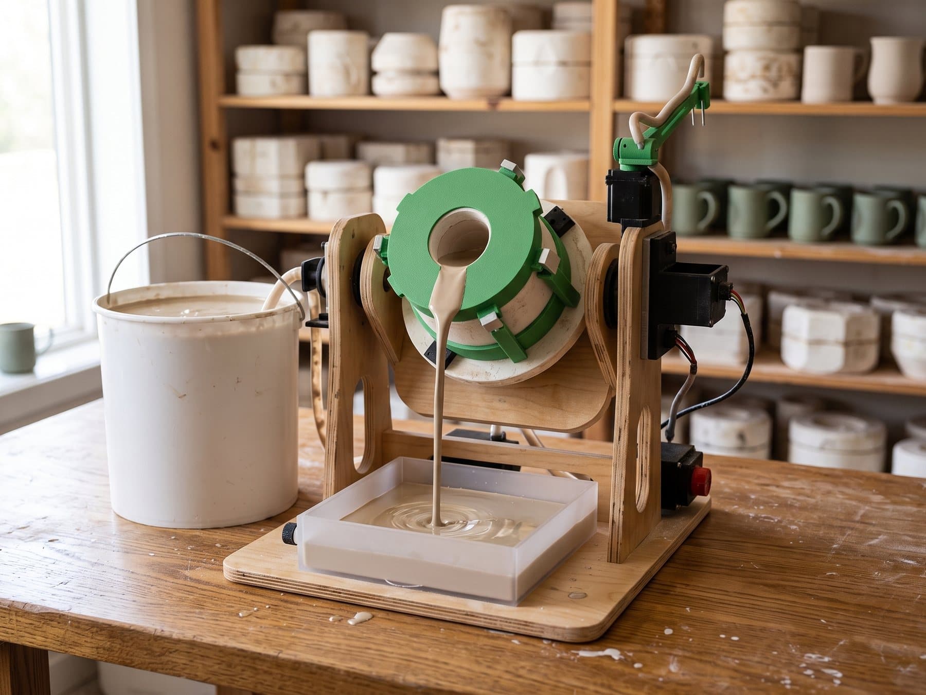
- The shop floor is missing a jig, template, holder or guard that is currently improvised.
- You want to merge several bolted parts into one, or lighten a heavy part with a lattice structure.
- You are starting with 3D printing but expect volumes to grow and the part to move to CNC, sheet metal or injection moulding.
What you get
- A CAD model in STEP, ready for printing, machining or further work by your own engineer.
- Print files (STL, 3MF), with the orientation set where it matters.
- A PDF technical drawing, with dimensions and tolerances only where they are needed.
- A process and material recommendation for now and for higher volumes.
- For enclosures: a mechanical spec for the boards (outlines, positions, connectors, fixings).
- Optionally a test version, finished parts and renders from the model.
How we work
Typical lead times for simple and medium geometry. For larger projects, the lead time is part of the quote.
- 01
Brief and inputs
Send whatever you have: a sketch, photos with a ruler, an old model, a description of the job. We reply within 1 working day with questions and a quote.
- 02
Measuring and CAD model
We measure or scan whatever the part has to fit and build a parametric model. Measurement, 3D model (STEP) and drawing usually take 2 to 5 days.
- 03
Choosing the process
For every part we say what to make it in now and at higher volumes, and why. The geometry is shaped for that process from the start.
- 04
Test version
We print a plastic version in 2 to 4 days so you can offer it up in place. Corrections go into the model, not into another round of guesswork.
- 05
Files and production
You get the full set of files and drawings. We can also make the part: FDM in-house, MJF and SLS in 3 to 5 working days, CNC, sheet metal and moulding through trusted shops.
Designed for the process, not for one print
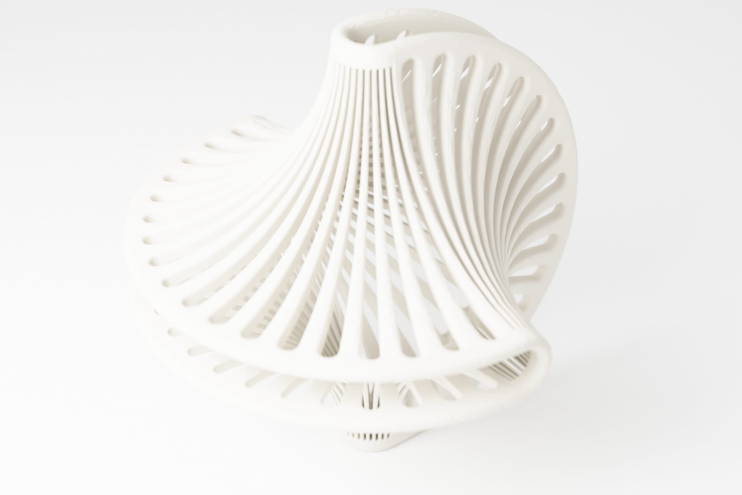
Every process has its own rules. In FDM, what matters is orientation on the bed, overhangs and which way the part will be loaded. MJF and SLS (PA12 powder) need no supports, so they allow internal channels, snap fits, lattice structures and merging several parts into one. Resin gives fine detail. When volumes grow, the same part moves to CNC, laser cutting and bending, or injection moulding, and then it needs draft angles, even walls and a sensible split into components. We design with that step in mind, so moving on does not mean starting over.
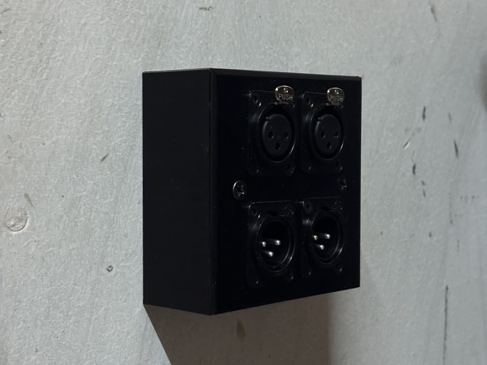
We design electronics enclosures together with the electronics: we know where the board sits, where the cable runs, how the connector comes out and how it all comes apart for servicing. For fixings we use heat-set inserts rather than a screw into bare plastic. MJF and SLS tolerance is typically ±0.3 % (no less than ±0.3 mm), so clearances and fits are calculated for the actual process.
Frequently asked questions
How much does it cost to design a part for 3D printing?
It depends on what you bring (a finished model, a sketch or just a photo), how complex the geometry is and how many parts have to work together. We do not publish a price list, because two similar-looking parts can differ a lot. You get a quote within 1 working day of sending your materials.
Can you design a part without a drawing, from a photo or sketch?
Yes, that is a common starting point. We take the critical dimensions from measuring or scanning whatever the part has to fit, and agree the rest with you. Before the final print we make a test version, so nothing is left to guesswork.
What is DfAM and how is it different from ordinary CAD design?
DfAM (design for additive manufacturing) is design that accounts for how the part will be printed: orientation, walls, supports, clearances and material. The result is parts that fit first time, weigh less and often replace several components with one. A CAD model drawn for machining usually needs reworking before it prints well.
How long does a design take?
For simple and medium geometry, measurement, 3D model (STEP) and drawing usually take 2 to 5 days, and a plastic test version another 2 to 4 days. Larger projects, such as an enclosure with electronics or a whole workstation, get a lead time in the quote.
Do you design custom electronics enclosures?
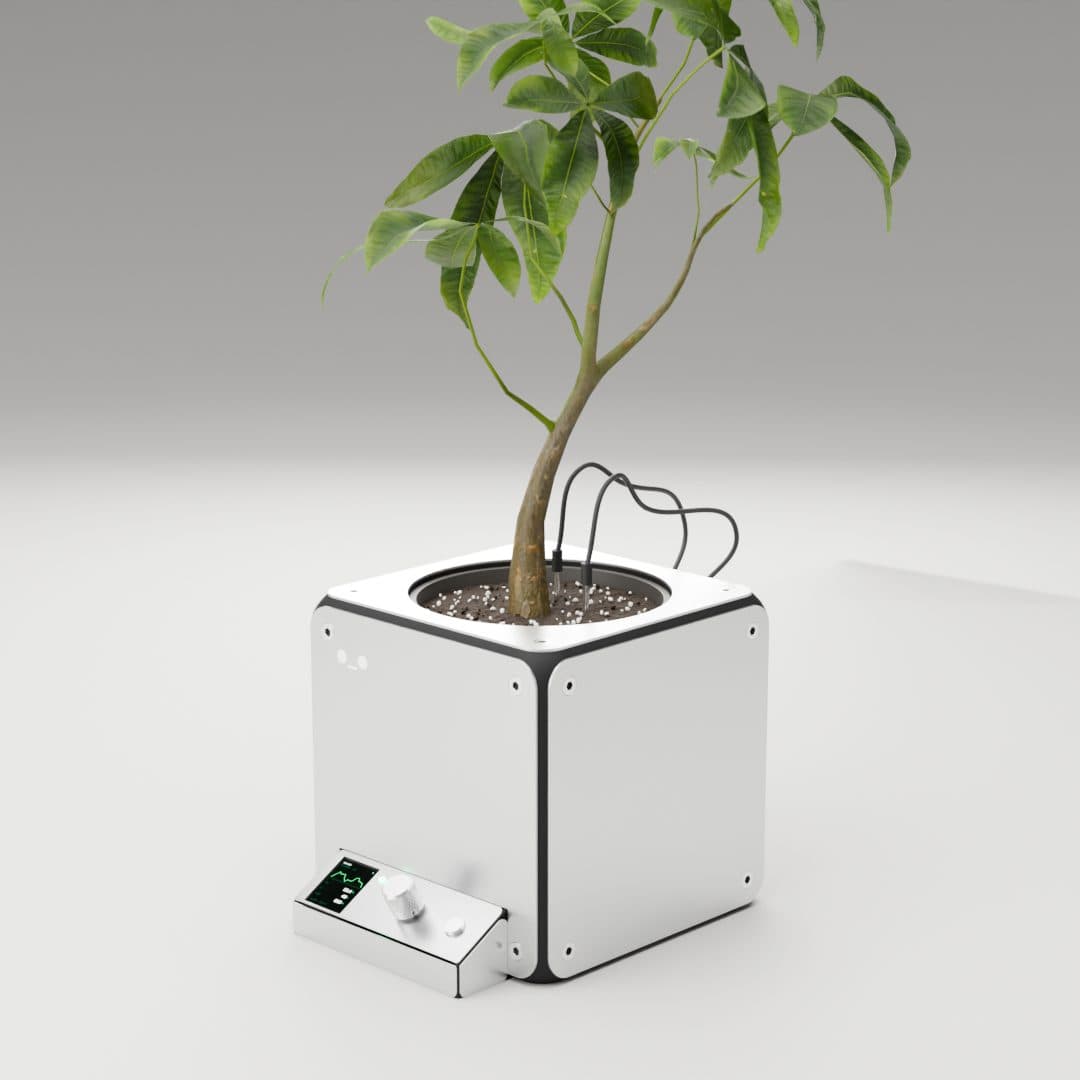
Yes, ideally together with the electronics. We lay the enclosure out around the boards, connectors, cables and servicing, and if the boards do not exist yet, we prepare a mechanical spec for the electronics to be designed against. We also design the product electronics themselves.
Can a design for 3D printing later move to CNC or injection moulding?
Yes, if we know from the start that volumes will grow. We then design with draft angles, even walls and a sensible split into components, and prepare documentation for machining, sheet metal or a mould. Production goes to trusted shops in Poland.
Do you sign an NDA, and who owns the files?
We sign a confidentiality agreement on request. Files go only to the shop making the part, and we never publish a project without your consent. When the design is done, you get the full set of source files and drawings.
Do you also just print from a ready file?
Yes, but we always check the file first. If something will not work (walls, clearances, orientation), we tell you before printing, not after. You gain the most when design and production are in the same hands.
More in the knowledge base

FDM, MJF, SLS: when plastic can replace metal, and when it cannot
3D printing will not replace the steel in a machine frame. It does, more and more often, replace machined covers, brackets and adapters. A short guide: technologies, materials and five questions that settle the choice.
Workshop tooling from a 3D printer: fixtures, templates, covers, signage
Every shop floor has things improvised on the spot. 3D printing turns them into proper, repeatable tools within days, with no mould and no minimum order. What works, what to make it from, and where the limits are.
Other services
Have an idea, a sketch or a part that does not work?
Send what you have: photos, a sketch, a file, a description of the job. Within 1 working day we will tell you how to design it, what to make it in and what it will cost.