Kiteboard handles: one design for 170, 180 and 200 mm screw spacings
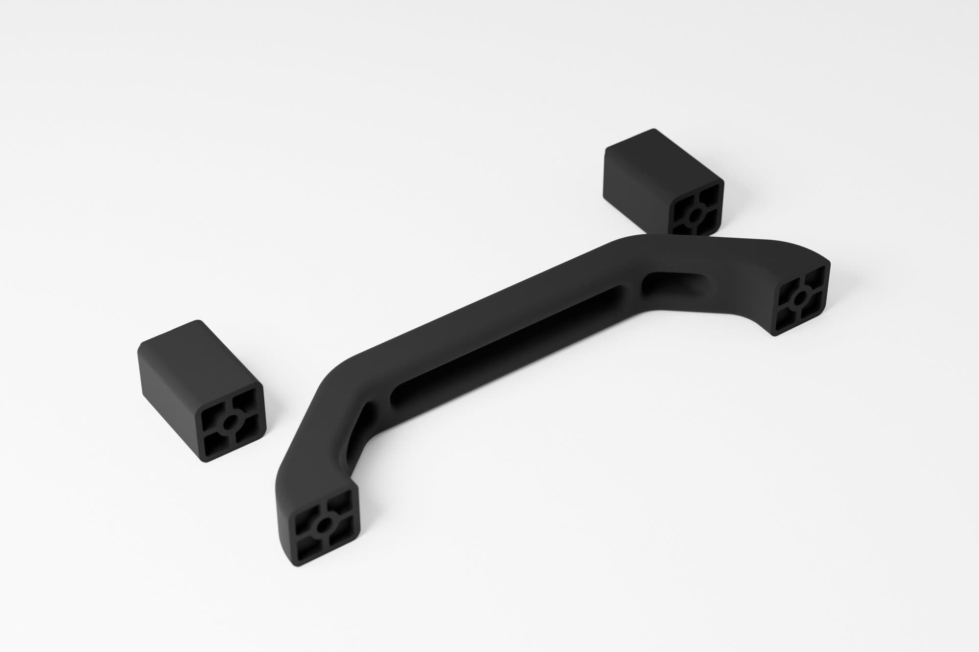
Our own kiteboard handle that grew out of time on the water and later went to a board manufacturer. One profile in three screw spacings (170, 180 and 200 mm), 40 mm spacers that raise the handle on any board with that spacing, a clip-mount variant and FDM printing in carbon-fibre PETG. From the first model to a boxed kit: handle, spacers and screws.
Problem
The handle on a kiteboard is a small part that a lot depends on. A rider taking the board off their feet mid-jump wants to grab it quickly and firmly, and a stock handle is often low and hard to reach. Every board brand has its own screw spacing, so one handle does not fit everywhere. The part works in salt water and sun, takes knocks and yanks, and the mounting must not work loose. Then came a request from a board manufacturer: a prototype matched to their own mounting that can be tightened by hand.
Outcome
A family of handles for three screw spacings (170, 180 and 200 mm), 40 mm spacers to raise an existing handle and a clip-mount variant for a board manufacturer. All from one parametric model, with technical drawings and files ready to print again. The handles were ridden on boards during on-water tests, and the same file is prepared for powder printing when a production run comes.
- 01A need from the water. The idea came from running a kitesurfing school: a taller handle that is easier to reach in the air. The first version was made in December 2024, the next ones every few weeks, after each trial on a board.
- 02One profile, three spacings. The model is parametric on hole spacing: 170, 180 and 200 mm, giving handles 195, 206 and 226 mm long. The M6 screw holes are counterbored, so the heads sit inside the feet. A new spacing is a new value in the model, not a new design.
- 03Spacers instead of a new handle. A second answer to the same problem: 40 mm spacers that go under the handle feet and are fixed with longer screws. They raise the handle on any board with a supported spacing, without replacing the whole part.
- 04FDM printing tuned for load. We print the handles on a Bambu Lab X1C in carbon-fibre PETG: 0.16 mm layers, 8 perimeters and 65% gyroid infill. The part lies on its side so the layers follow the arch, and small discs at the corners hold it to the bed for the whole print.
- 05A variant for a board manufacturer. At a manufacturer's request we built a prototype for their mounting: a clip-on handle with a hand-tightened insert, plus a tall, thick 95 mm handle on a 180 mm spacing. Along with technical drawings and production files.
- 06Kit and further production. The handle, two spacers and the screws go into one box. We have also prepared the same model for MJF / SLS powder printing at a partner, for a run where a smooth surface and repeatability matter.
Specifications
IE-001- Screw spacing
- 170 / 180 / 200 mm
- Mounting
- M6, counterbored; clip-on variant
- Spacers
- 40 mm, on longer screws
- Printing
- FDM, Bambu Lab X1C, 0.16 mm layers
- Material
- Carbon-fibre PETG (PETG-CF)
- Series
- Model prepared for MJF / SLS