A worm gear set for a machine tool: from measuring the original to drawings for a CNC shop
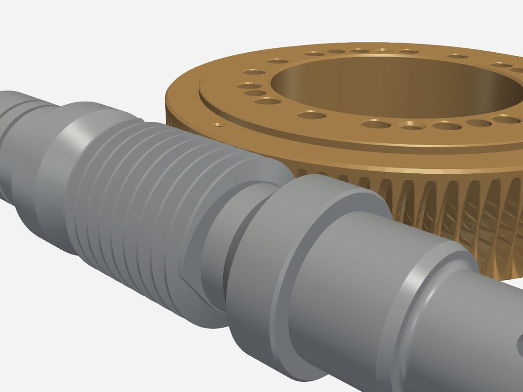
A spare worm gear set for a machining centre: a bronze worm wheel with 90 teeth and a split steel worm. There are no drawings, and a CNC shop wanted to make these sets itself, outside the machine maker's service. We rebuilt the production documentation from the original in 9 days: caliper and photo measurements, a parametric model, a hobbing simulation and a contact-pattern simulation, 69 model tests, 4 A3 sheets and STEP files.
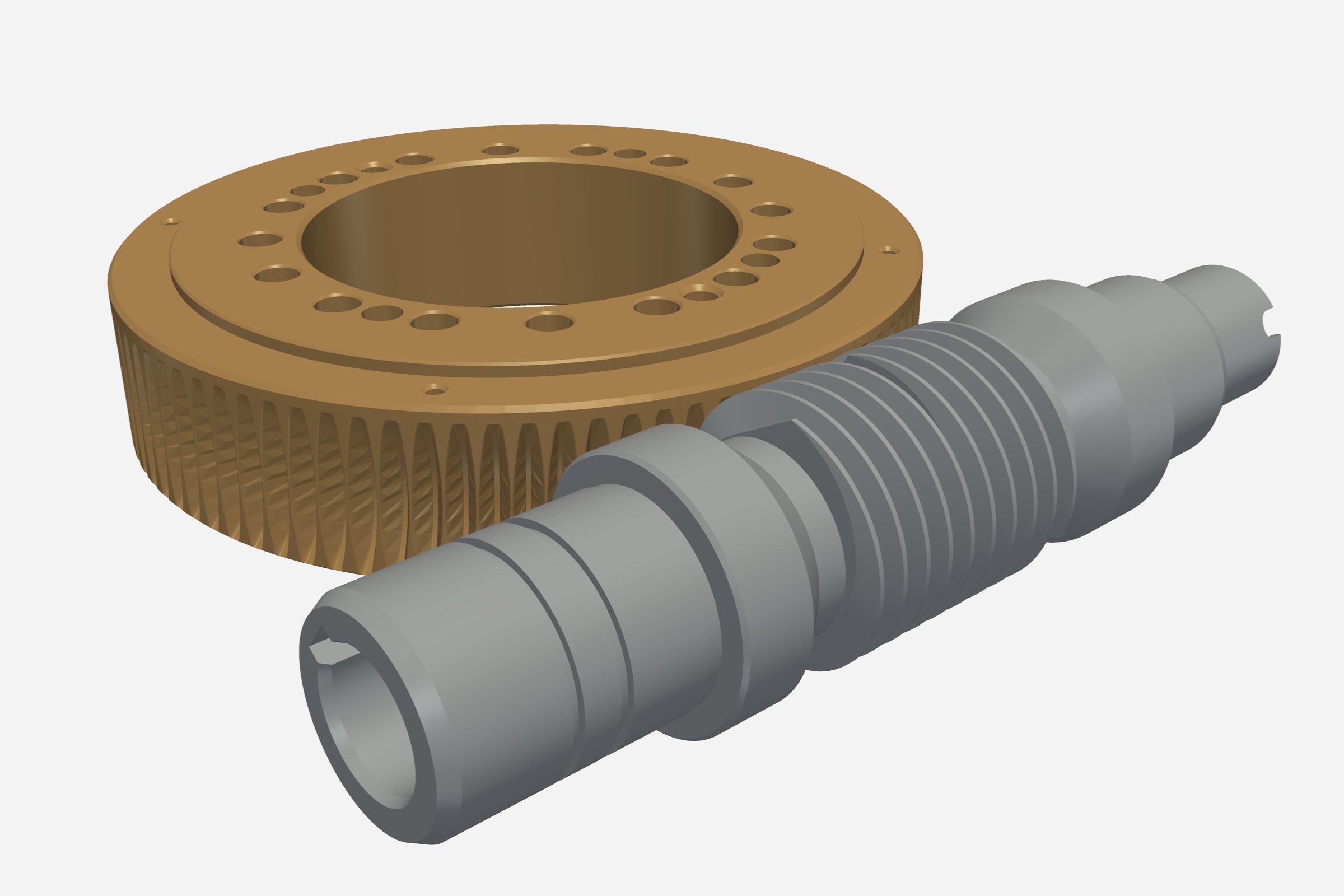
From the original to the documentation
06- 01
Measurement
about 90 positions
Calipers, 3 readings 120° apart, plus photos on a measuring mat.
- 02
Parametric model
one data set
Pitch, module, profile angle and centre distance drive every part.
- 03
Hobbing
simulated, 1° steps
Grooves cut by a hob matching the worm, not drawn.
- 04
Meshing
1:90 ratio
0.0 mm³ collision, 0.03 mm smallest clearance.
- 05
Contact pattern
1.9 million points
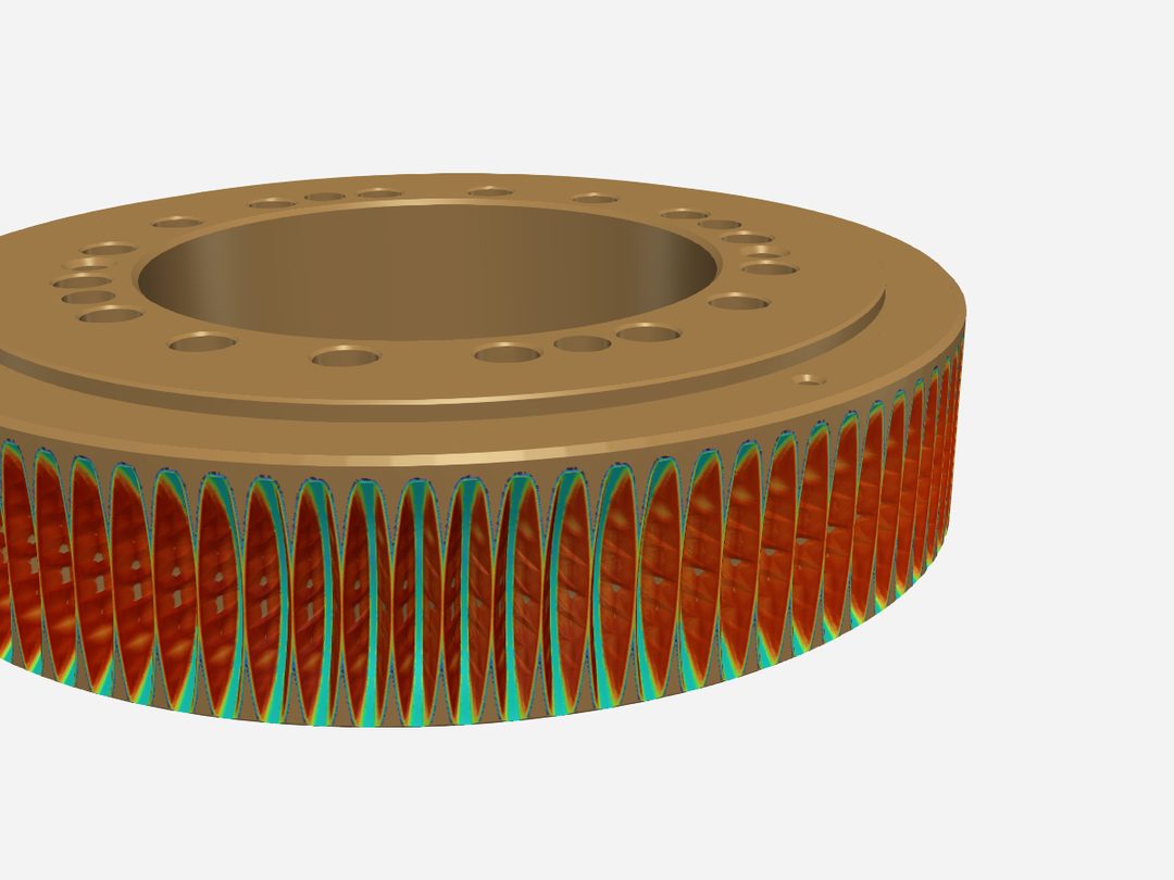
Flanks in contact over the full height, root with tip clearance.
- 06
Documentation
4 A3 sheets and STEP
69 of 69 tests, 4 independent checks, 8 points to confirm.
Problem
A worm gear looks simple, but most of its geometry cannot be measured with calipers. The worm pitch, the profile angle, the wheel's profile shift and the centre distance have to be worked out from several measurements at once, and a mistake only shows on the machine, when the pair refuses to mesh. The worm is split: a shaft and a sleeve slid over it take up the backlash, so both threads must form one continuous helix. The wheel grooves are hobbed, so their shape cannot simply be drawn. We had the original for only a few days, and it came with no documentation at all.
Outcome
The shop received everything it needs to make the pair without the original: drawings of the shaft, the sleeve and the wheel, STEP models, a report giving the source of every dimension and a list of things to check with a micrometer before the first part. We do not machine the metal ourselves: we prepare the documentation, and the machining stays with the CNC shop. The same method works for any worn or unavailable machine part with no drawing: gears, worms, shafts, sleeves and flanges.
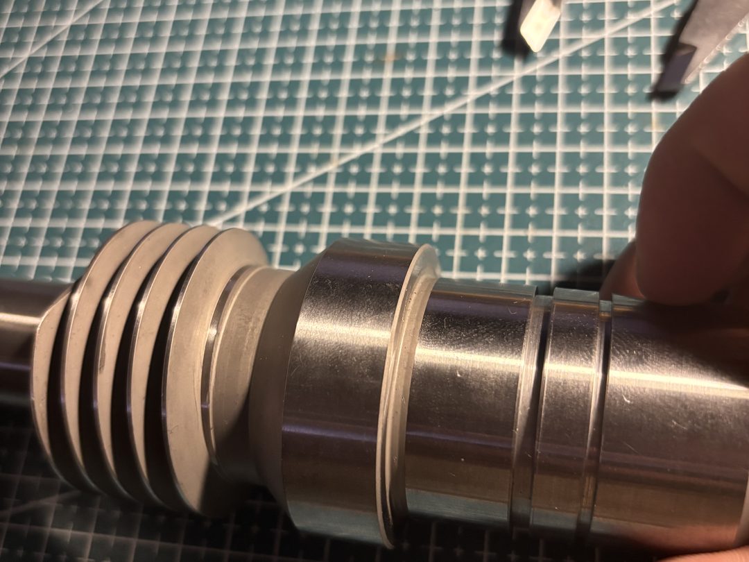
- 01Measurement. A measuring card with diagrams of what to measure and how: about 90 positions, every diameter taken 3 times with calipers, 120° apart. Wherever the measurement and the photos disagreed, we measured again (9 positions).
- 02Measuring from photos. The parts are photographed on a measuring mat, with scale taken from a caliper dimension in the same plane, perspective correction and edge analysis at full resolution. That is how we checked the layout of the wheel's 22 holes (angles within 0.18°), the groove shape and the thread ends. The worm pitch was also checked with a clay imprint, independently of the calipers.
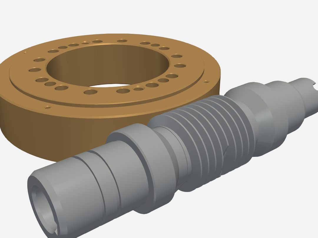
- 03Parametric model. One set of gear data (pitch 5.70 mm, module 1.8144, profile angle 14.5°, centre distance 106.81 mm, worm axis 16.5 mm above the wheel's bottom face) drives the shaft, the sleeve, the wheel and the assembly. Changing one number rebuilds the whole pair consistently.
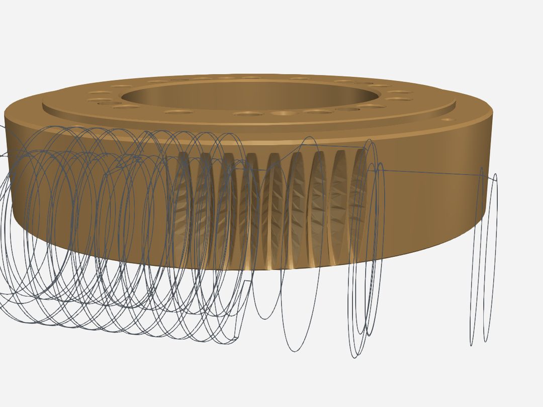
- 04Hobbing simulation. We do not draw the wheel grooves, we cut them in a simulation with a hob matching the worm, step by step at 1° of rotation. Profile angles of 17.5° and 20° were ruled out by comparing them with the original's geometry. The 14.5° we adopted is marked on the drawing as one to confirm before production.
- 05Meshing simulation. The worm turns through 4 full revolutions in 3° steps, the wheel at a 1:90 ratio. For 1.9 million points on the tooth flanks we compute the smallest clearance over the whole cycle: the flanks work over the full groove height, the root keeps its tip clearance, and the smallest clearance is 0.03 mm with no collision at all. With the rotation reversed the thread cuts into the wheel, so the simulation tells correct kinematics from wrong.
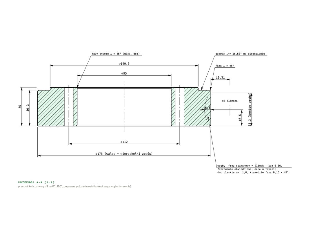
- 06Checks and drawings. 69 automated tests compare every measured dimension with the STEP model. Before handover, four independent checks: the model against its parameters, new measurements from the photos, the gear geometry recomputed from scratch and the drawings against the model. Finally 4 A3 sheets with tolerances, a gear data table and a list of 8 points to verify before the first part.
Specifications
IE-034- Part
- Worm gear set: z2 = 90 wheel, split worm
- Gearing
- Pitch 5.70 mm, profile angle 14.5°, centre distance 106.81 mm
- Measurement
- Calipers (about 90 positions) and photos on a measuring mat
- Simulations
- Hobbing, contact pattern, collisions
- Checks
- 69 of 69 tests, 4 independent checks
- Delivered
- 4 A3 sheets, STEP, report, in 9 days