When calipers are not enough: measurement, hypothesis and simulation in rebuilding machine parts
The most important dimensions of a worn part often cannot be measured directly. Using a worm gear set for a machine tool as the example, we show a method that also works for gears, shafts, sleeves and castings.
In short
- We sort dimensions into three groups: directly measurable, inferred from several measurements, and left by the tool. Each needs a different method.
- We establish key parameters in at least two independent ways. A disagreement is information, not noise.
- Shapes made by tool motion are not drawn, we simulate that motion. We also check the pair at work in simulation.
- What cannot be settled goes on a list to confirm. Honest uncertainty is cheaper than false certainty.
For a simple bracket, careful measuring is enough. For a part that works with something else, the important dimensions usually do not sit on the surface: pitch, profile angle, profile shift, centre distance, a shape left by the cutting tool. Calipers will not show them. They have to be inferred, and then proven.
We show it on a spare worm gear set for a machining centre: a bronze worm wheel and a split steel worm, with no drawings at all. The gear set is only the example. The method is what counts.
Three kinds of dimensions
Before we measure anything, we sort the dimensions into three groups. A single worm shaft has all three.
- 1Directly measurable
Spigot and journal
Diameter and length. Calipers, 3 readings 120° apart, because wear is rarely even.
- 2Inferred
Thread
Pitch, module, profile angle. None can be read off one scale. They follow from several measurements at once.
- 3From the process
Grooves and undercuts
Their shape comes from the tool, e.g. a grinding wheel run-out. We rebuild it from the standard and the measurement, not by eye.
Several independent methods instead of one
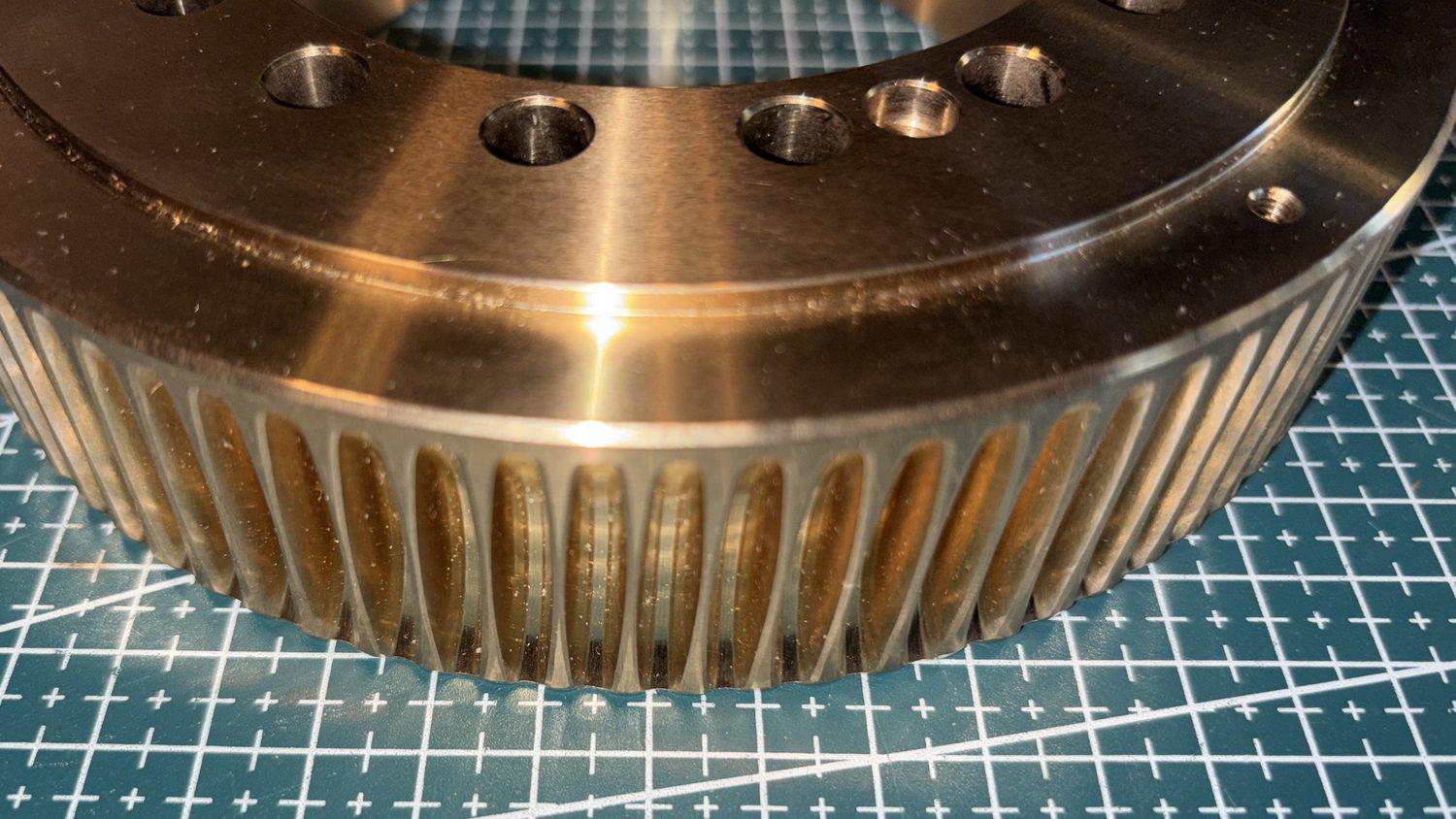
We establish every key parameter in at least two ways that share no common source of error: calipers following a measuring card (about 90 positions), photos on a measuring mat with scale and perspective correction, and, for the worm pitch, a clay imprint as well.
This is what the road to a single number, the worm pitch, looked like. The first assumption was convenient and round. The clay contradicted it, so we paused the model and waited for a measurement on the metal.
- 01
Assumption
Photos and the wheel diameter give a round, convenient number. It fits everything.
- 02
Clay
The imprint gives clearly less. Instead of blaming the clay, we pause the model.
- 03
Metal
Measuring over several pitches, on the shaft and the sleeve. The clay was right, the assumption goes.
- 04
Measuring machine
A coordinate measurement at the shop confirms the result to the thousandth.
Why did the wheel diameter mislead? The wheel had a profile shift, so its outside diameter does not directly tell you the module. This trap has cousins everywhere: a worn surface, one that was re-turned, casting shrinkage, a coating. A dimension that looks like a design dimension does not have to be one.
A parametric model: one table, every part
The shaft, the sleeve, the wheel and the assembly all come from one set of gear data. Changing one number rebuilds the whole thing consistently. In the first version, the wheel and the worm had separate, slightly different numbers: each part looked fine, but together they would not have worked.
The model review also caught an error no render shows: the wheel grooves had the right inclination, but the wrong way. A collision test showed it immediately: over 100 mm³ of interpenetration in the wrong direction, zero in the right one.
A process shape is not drawn, it is simulated
Worm wheel grooves are made by hobbing: a cutter shaped like the worm rotates together with the wheel and generates the teeth by motion. So we cut them in a simulation with the same motion, step by step, and compare with the original. That is how two other profile angles, both plausible on paper, were ruled out.
The same goes for any shape that is the trace of a tool's motion: shaped gears, rolled threads, cams, splines. Drawn by eye, it will look similar. Generated by motion, it will be the same.
Simulating the part at work, not just its shape
A pair that looks right may still fail to mesh. So we turn it in a simulation: the worm through several full revolutions, the wheel at its ratio, and at every position we compute the clearance on the tooth flanks.
- 1.9 million
- points on the tooth flanks
- 0
- collisions in the correct direction
- 159
- penetrating points with the direction reversed
Testing the model like software
Every measured dimension has an automated test that measures it in the finished STEP file, the way the calipers measured the original. On top of that, four independent checks before handover. After every change we run everything again, because nobody checks a hundred dimensions by hand after each fix.
- 01
Model against parameters
Does the STEP solid carry exactly the numbers in the table.
- 02
New photo measurements
A second, independent reading of the same dimensions.
- 03
Gearing from scratch
The pair's geometry recomputed without using the model.
- 04
Drawings against the model
Every dimension on the sheet checked in the solid.
A list to confirm, and a second revision
The first version of the documentation went to the shop with a list of 8 points to check before the first part, including gear parameters that calipers cannot settle. The shop measured the original on a coordinate measuring machine and with micrometers. Some values moved by hundredths of a millimetre, the profile angle by a fraction of a degree. Thanks to the parametric model, we entered the new numbers, recomputed the hobbing and the meshing and ran the tests.
- 8
- points to confirm in the first version
- 43
- positions from the shop's measurements checked on the drawings
- 0
- discrepancies after the second revision
- 97
- model tests after the second revision (was 69)
Where else the method works
Gears
Spur, helical, bevel, racks. Especially with profile shift or a non-standard module.
Shafts and sleeves
Fits, grinding undercuts, keyways, steps.
Unusual threads
Trapezoidal, multi-start, left-hand, imperial threads on old machines.
Cams and splines
Shapes made by tool motion that have to be generated, not drawn.
Castings and flanges
Hole patterns, where matching the mating part is what counts.
Mechanisms
Hinges, latches, slides: collisions checked over the full range of motion.
What the method does not replace
- A strength analysis without known loads. Without them we do not compute stresses, and we do not pretend to.
- Identifying the material and heat treatment. The grade and hardness are set by the shop or a lab.
- First article inspection. The documentation says what to measure and where, but the metal has the final word.
How to start
A photo of the part, a few sentences about what it works with, and who will make it are enough. We do not machine metal ourselves: we prepare the documentation, and the machining stays in your shop or with a partner. We reply within one working day.